Introduction
Name: Kevin Mangan(A16)
Tutor: Ted
Student number: C16376711
Team number: 4
Team name: MJK robotics
I was part of team 4 which consisted of myself, Mark O’Byrne and Jonathan Nally. I did not know the two lads before this project and they were both friends but they were very welcoming. They both had a back round in engineering(leaving cert) and Mark had a good understanding of coding. I was not so lucky but the lads were very helpful and patient in explaining what was going on and why.
In week one we met in the lecture hall KE3-008(as we would do every week) and the layout of the project was set out and what we would do in the following lab was explained.
- Week 1 : Form teams, create blogs, begin LED Flash Challenge.
- Week 2 : Complete LED Flash Challenge
- Weeks 3-5: Robot design and build.
- Weeks 6-7: Race to the Wall competition.
- Weeks 8-11: Robot design and build.
- Week 12: RoboSumo tournament.
Week 1-2 LED Flash Challenge
In week 1 we were given our RoboSumo kit included the following items:
- 1 x mini breadboard
- 1 x MSP430 LaunchPad
- 1 x mini USB cable
- 1 x MSP430G2452 microcontroller (or MSP430G2553)
- 1 x 4AA battery holder with built-in switch
- 2 x yellow geared DC motor
- 1 x SN754410NE driver chip
- 1 x LM1117 3.3V voltage regulator
- 4 x TCRT5000 infrared reflective sensor
- 1 x microswitch
- 1 x 1000uF electrolytic capacitor
- 4 x green LED
- 4 x red LED
- 8 x 220 Ohm resistor
- 4 x 10 kOhm resistor
- 2 x 100 kOhm resistor
The main objective of the LED Flash challenge is the following.
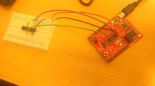
- Build a simple breadboard circuit for the MSP430 microcontroller and program it to blink an LED on and off.
- Add a second LED to the circuit and reprogram the MSP430 to transmit a specific binary sequence as a series of flashes from the two LED.
Getting it working quickly and trying to understand what you’re doing was also important.
Part 1: Blinking LED
MSP430

We are using the individual bits (digits) of binary numbers to switch different pins on and off on the micro controller. Port 1 consists of the following 8 pins: P1.0, P1.1, P1.2, P1.3, P1.4, P1.5, P1.6, P1.7 and Port 2 consists of the following 8 pins: P2.0, P2.1, P2.2, P2.3, P2.4, P2.5, P2.6, P2.7.
The power source comes from the computer its connected to. 
Part 2: LED Flash Challenge
Binary code
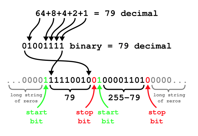
4 = 00000100
251=11111011
000001001000000111011111000000
cycles seconds
5000000 = 5.9
500000 = 0.59
423728 = 0.5

As you can see the binary code is on the right of the picture in the green. The delay cycle is 4237280(on for 5 seconds) for the first one to show were ready to start and then the rest are 423728(0.5 seconds).
0b00000010 = on 0b00000001=off
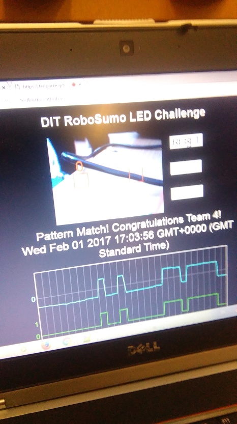
The picture above is the validation station where we recorded our results and made sure we had the right code.
Weeks 3-5: Robot design and build for Race to the Wall
Rules
- The dimensions of a robot cannot expand outside its 10cm x 10cm footprint at any time during a race.
- The robot’s mass must not exceed 0.5kg.
- Break the start/finish laser beam once and only once (the first of two times during the race),
- Continue moving forward until it touches a block,
- Move back towards the start/finish line,
- Stop on the start/finish line within the 20 second time limit, breaking the start/finish laser beam for the second and final time. The beam must remain continuously broken for a minimum of 2 seconds.
- Once the robot is activated, team members may not intervene or interfere with it in any way for the full duration of the task
- Any teams that complete the challenge for the first time in week 7 will be ranked below all teams that complete the challenge in week 6.
- The highest ranked teams will be those that complete the Race to the Wall task in week 6 and are fully compliant with the weight and size restrictions (see below). These teams will be ranked in ascending order of recorded time.
- The next ranked set of teams will be those that complete the task in week 6 but are not fully compliant

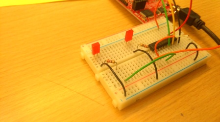
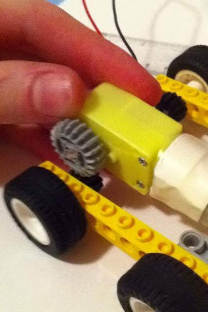
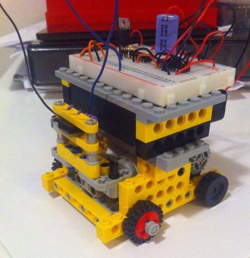
The Construction of the Robot
We first constructed the bread board. The red wires are connected to the 6v battery source and the black wires are connected to ground. The orange wires are a 3.3v suplly coming from the LM1117 3.3V voltage regulator.


There was two very important attachments on the robot. The Infrared Reflective Sensor
(TCRT5000) and the switch input.
TCRT5000


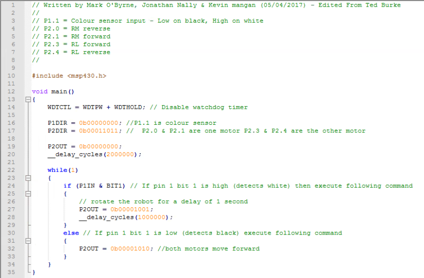
When the current flows infrared light is emitted from the diode. The IR light reflects off a surface and back to the phototransistor which then allows current to flow through it. This is how we are going to stop the robot on the line as it will not reflect off the black surface.
Code

Switch input
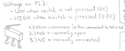
When the switch is up voltage goes from 1-3. When switch is down voltage goes from 1-2.
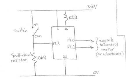
We use the switch so that when we hit the wall it triggers the motors to turn the other way.
Code
We first tried to understand how the motors worked.
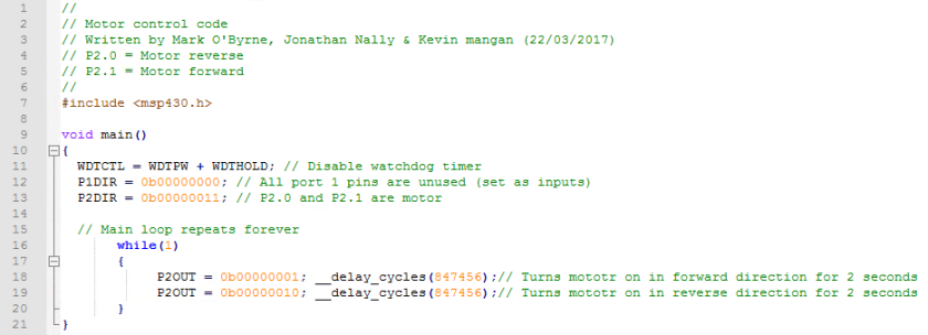

Race to the wall code

Construction of robot

Race to the Wall competition
Conclusion
Race to the wall was a success as we were one of the first teams to complete the challenge but if I was doing it again i would do some things differently.
- tidy up wires on top as they made us non-complient
- use more powerful motors as our robot was very slow
- use bigger wheels as this would increase speed.
Weeks 8-11: Robot design and build for Robosumo tournament
We decided to strip our robot down and start a new design for the robosumo tournament as there are different needs and commands the robot must follow.
Rules
- The dimensions of a robot cannot expand outside its 10cm x 10cm footprint at any time during a race.
- The robot’s mass must not exceed 0.5kg.
- Teams position and start their robots manually at the beginning of each bout, as instructed by the referee.
- Each robot should remain still for at least 2 seconds
- The duration of each bout is limited to 60 seconds. If both robots remain the winner based on each robot’s distance from the centre of the table (the closer the better), robot activity/behaviour during the bout.
- Dimensions of each arena is 77cm diameter with a 2.5cm white border
- Each team’s robot spending limit is €70
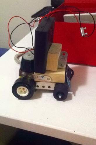
We designed a few different robots and decided as a team which one we would use for the tournament.
Design 1

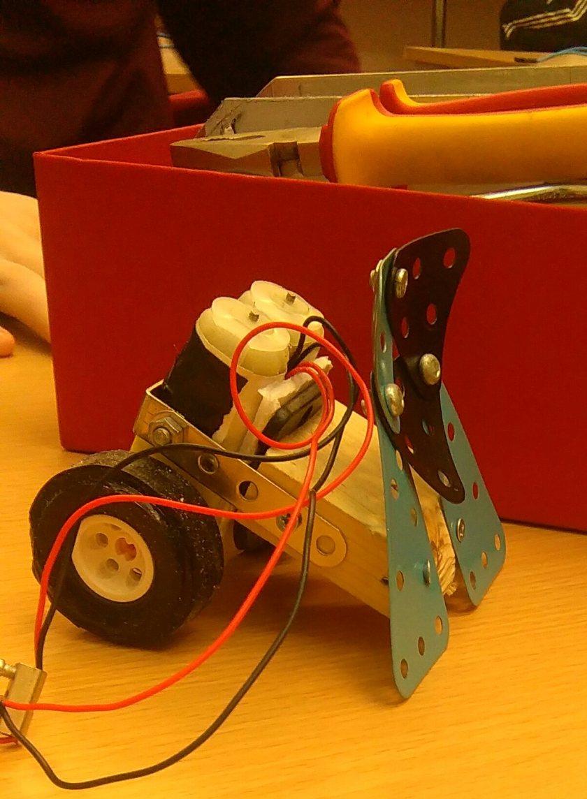
Design 2
Design 3

Design 4
We went with design 4 as the design of it gave it the greatest pushing power, it turned very well and it would fit the requirements. The only negative with the design was that it was very light and we needed more weight at the front to stop it toppling.
Final Design
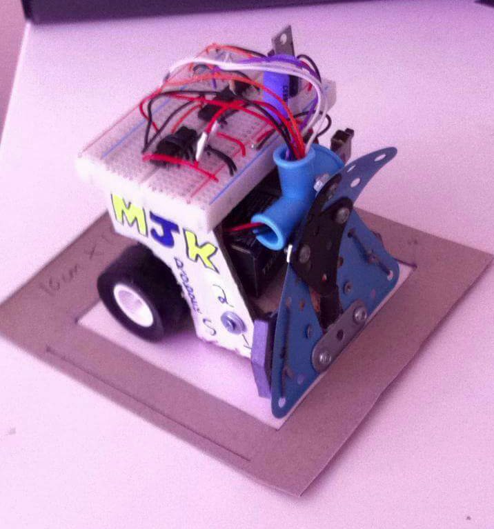
As you can see we added weight at the front by connecting fish weights to it. We also used a 9v battery to increase pushing power further. The TCRT5000 is at the very front to detect when we are near the edge.
The Code
Testing the robot
We were the first group to get a robot working properly the only disadvantage we had is that it could only turn one way.
Week 12: RoboSumo tournament
The start of the tournament went horribly wrong as our sensor was not working and we could not understand why because of this we lost are first three battles.
Mark found out that the sensor was to close to the ground and after this we started winning. In round 16 we were match against a robot who won it so really had no chance of progressing.
Conclusion
Overall I think both are robots did very well and ranked highly. I really enjoyed this module and found it very interesting. I have to give a lot of credit to my team mates especially Mark as he did most/all the coding but he was very helpful in explaining it a did not go off with the computer by himself as he could of done. My main jobs were in the construction part and taking photos and videos of what were doing. this module helped me pick what I want to do next year. It pushed me away from electronics and towards civil and structural.

